Pressure Vessel
FEA Analysis
ASME Section VIII Division 2 finite element analysis — four failure modes, oval nozzle qualification, and PE-sealed report for a Southeast Texas industrial facility.
When code formulas aren't enough
Grey Engineering Enterprises performed ASME Section VIII Division 2 Part 5 finite element analysis for a pressure vessel at a Southeast Texas industrial facility. The vessel featured oval nozzle openings — a geometry for which standard code formula methods are not applicable — requiring full FEA qualification.
The analysis was conducted using a shell element model (SHELL281, 8-node quadratic elements) with mesh refinement at nozzle junctions and reinforcing pad transitions. Symmetry boundary conditions were applied to reduce computational cost while preserving accuracy.
Operating conditions: 250 psig internal pressure at 200°F. Materials: SA-516 Gr 70 shell and SA-106 B nozzles. All four ASME Div. 2 failure modes were assessed and documented in a PE-sealed FEA report.
Request an FEA QuoteASME Sec. VIII Div. 2 FEA
Finite element analysis performed per ASME Section VIII Division 2 Part 5 — the advanced design-by-analysis standard. Shell element model (SHELL281, 8-node quadratic) built to capture membrane and bending stress distributions through the vessel wall.
Four Failure Mode Assessment
All four ASME Div. 2 failure modes evaluated: Plastic Collapse (limit load convergence), Local Failure (triaxial stress limit), Buckling (linear eigenvalue method), and Cyclic Loading (S-N fatigue curve). Each mode assessed against code-defined acceptance criteria.
Nozzle & Oval Opening Analysis
FEA of oval nozzle openings with reinforcing pad design — geometry where standard code formula methods are not applicable. Local stress concentrations at nozzle-to-shell junctions evaluated and compared against ASME allowables.
FEM Validation — Hoop Stress
Model accuracy validated by comparing FEA hoop stress results against closed-form hand calculations. FEA result (15,885 psi) matched hand calculation (16,000 psi) within 1% — confirming mesh quality and boundary condition accuracy before proceeding to nozzle analysis.
PE-Sealed FEA Report
Complete FEA report issued with mesh documentation, boundary conditions, load case definitions, stress linearization paths, and code acceptance criteria — sealed by a licensed Professional Engineer for owner and third-party review.
Four failure modes, all verified
ASME Section VIII Division 2 Part 5 requires evaluation of four distinct failure modes. Each mode uses a different analysis method and acceptance criterion. All four were assessed and passed for this vessel. Values shown are representative of the analysis methodology.
| Failure Mode | Analysis Method | Code Limit | Result | Status |
|---|---|---|---|---|
| Plastic Collapse | Limit Load Analysis — Convergence | Convergence | Converged | ✓ Pass |
| Local Failure | Triaxial Stress Limit (4×S) | 80 ksi | 71.75 ksi | ✓ Pass |
| Buckling | Linear Eigenvalue Method A | 9.08 ksi | 5.5 ksi | ✓ Pass |
| Cyclic Loading | Linear S-N Curve (Annex 5.B) | Design Life | 1,495 Cycles | ✓ Pass |
Representative values shown. Actual project results are proprietary. Analysis performed per ASME Section VIII Division 2 Part 5 (2023 Edition).
Mesh quality validated before analysis
Model accuracy was validated by comparing FEA hoop stress results against closed-form hand calculations before proceeding to nozzle analysis. The FEA result (15,885 psi) matched the hand calculation (16,000 psi) within 1% — confirming mesh quality and boundary condition accuracy.
Shell elements (SHELL281, 8-node quadratic) were used throughout, with mesh refinement at stress concentration regions. Far-field mesh size: 1 inch. Nozzle and reinforcing pad zones: 0.5 inch. Symmetry boundary conditions were applied to reduce model size while preserving accuracy at the critical nozzle-to-shell junction.
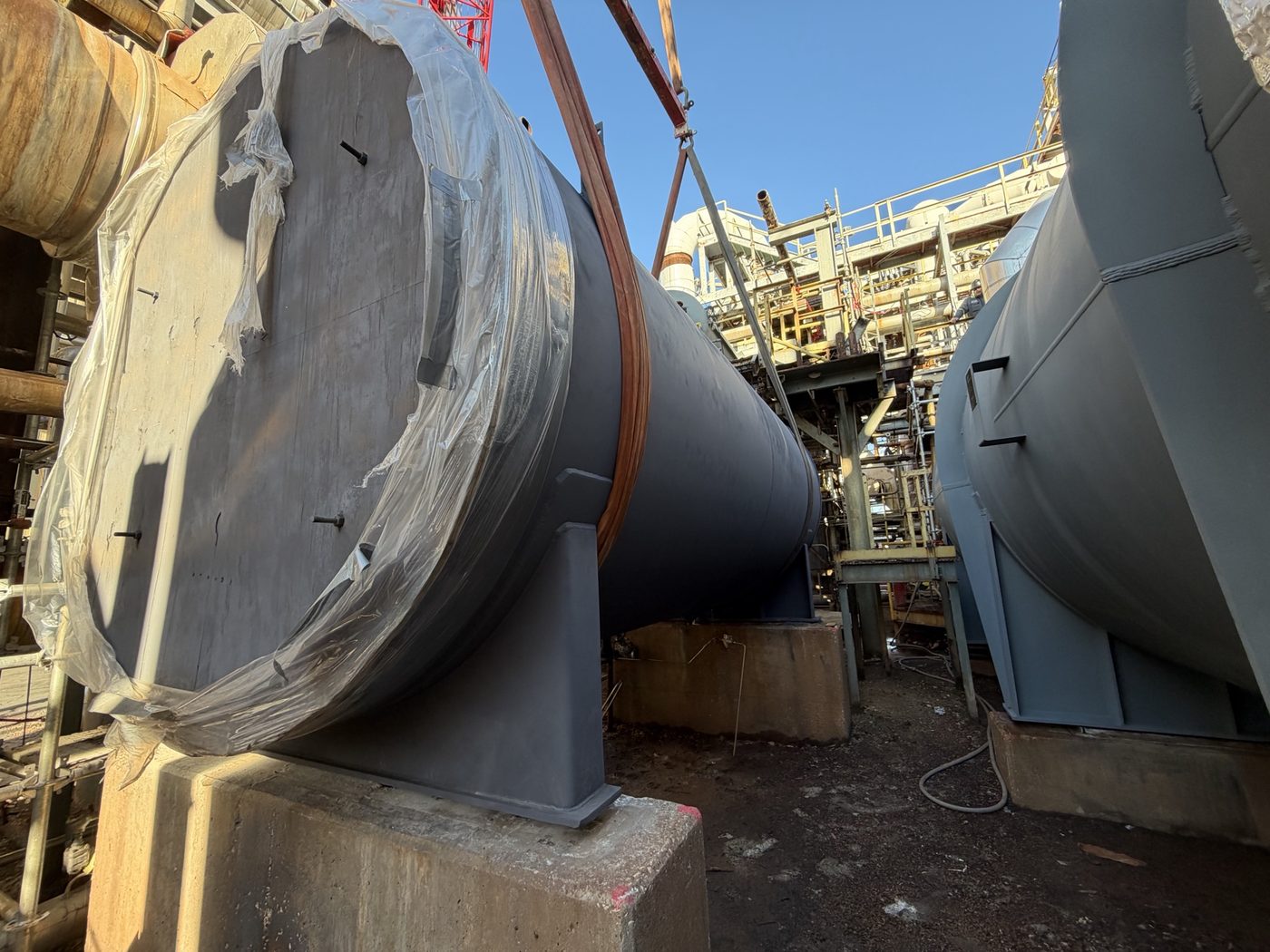
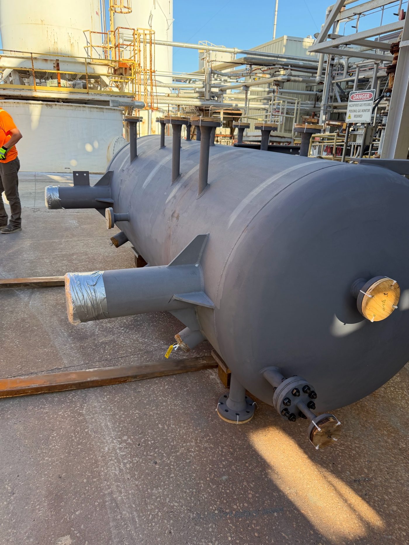
Vessels in the field